Digilent Arty Z7-20 APSoC Zynq-7000 Development Board
- RS庫存編號:
- 136-8071
- Distrelec 貨號:
- 300-83-920
- 製造零件編號:
- 410-346-20
- 製造商:
- Digilent

可享批量折扣
查看批量定價選項小計(1 件)*
TWD11,706.00
(不含稅)
TWD12,291.30
(含稅)
訂單超過 $1,300.00 免費送貨
有庫存
- 8 件準備從其他地點送貨
- 加上 10 件從 2026年8月28日 起發貨
- 加上 1 件從 2026年9月04日 起發貨
**需要更多嗎?**輸入您需要的數量,然後按一下「查看送貨日期」以查詢更多庫存和送貨詳細資訊。
單位 | 每單位 |
|---|---|
| 1 - 4 | TWD11,706.00 |
| 5 + | TWD11,472.00 |
* 參考價格
- RS庫存編號:
- 136-8071
- Distrelec 貨號:
- 300-83-920
- 製造零件編號:
- 410-346-20
- 製造商:
- Digilent
規格
產品概覽和技術數據資料表
法例與合規
產品詳細資訊
透過選取一個或多個屬性來查找類似產品。
選取全部 | 屬性 | 值 |
|---|---|---|
| 品牌 | Digilent | |
| Kit Name | Arty Z7-20 APSoC Zynq-7000 | |
| Product Type | Development Board | |
| Kit Classification | Development Board | |
| Processor Family Name | Cortex | |
| Standards/Approvals | RoHS | |
| 選取全部 | ||
|---|---|---|
品牌 Digilent | ||
Kit Name Arty Z7-20 APSoC Zynq-7000 | ||
Product Type Development Board | ||
Kit Classification Development Board | ||
Processor Family Name Cortex | ||
Standards/Approvals RoHS | ||
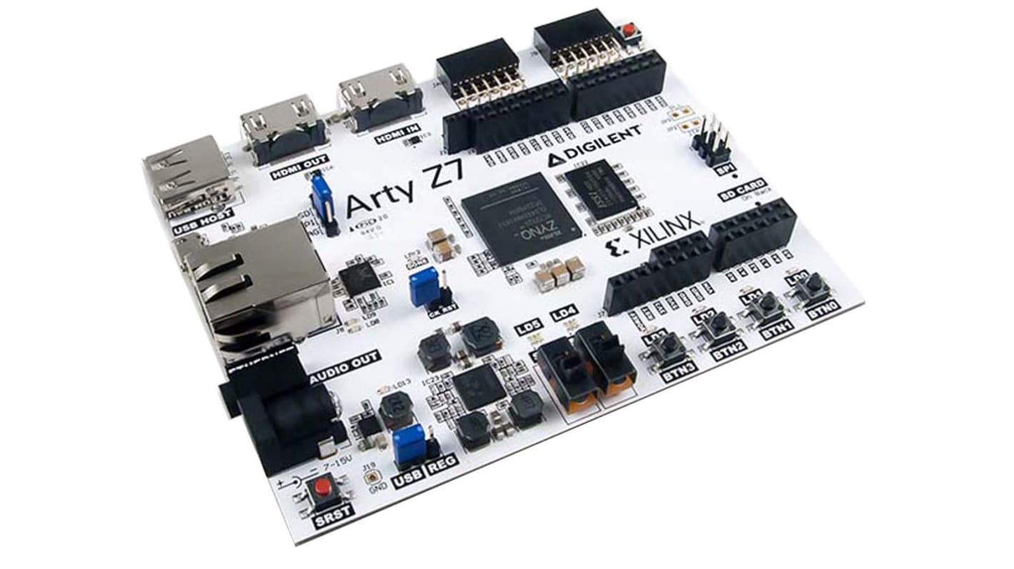
Arty Z7 Zynq-7000 Development Board
The Arty Z7-20 is a development platform designed around the Xilinx Zynq-7000™ All Programmable System-on-Chip (AP SoC). The Zynq-7000 architecture integrates a dual-core, 650MHz ARM Cortex-A9 processor with Artix-7 series FPGA logic. This pairing surrounds a powerful processor with a unique set of software defined peripherals and controllers. The Vivado, Petalinux, and SDSoC toolsets each provide a path between defining your custom peripheral set and bringing its functionality up to a Linux OS or 'bare-metal' program running on the processor.
Xilinx Zynq-7000 (XC7Z020-1CLG400C)
• Processor: 650MHz dual ARM Cortex-A9 core
• Look-up Tables (LUTs): 53200
• Flip-flops: 106400
• Block RAM: 630KB
• Clock Management Tiles: 4
• Available Shield I/O: 49
• DDR3 memory controller with 8 x DMA channels and 4 x AXI3 Slave ports
• High-bandwidth peripheral controllers: 1G Ethernet, USB 2.0, SDIO
• Low-bandwidth peripheral controller: SPI, UART, CAN, I²C
• Programmable from JTAG, Quad-SPI Flash or microSD card
• Programmable logic equivalent to Artix-7 FPGA Memory
Board Memory and Power
• On-board IS43TR16256A-125KBL 512MB DDR3 SDRAM with 16-bit bus @ 1050Mbps
• On-board S25FL128S 16MB Quad-SPI Flash with 48-bit unique EUI-48/64™ compatible identifier
• microSD card slot
• Powered from USB or +7V to +15Vdc via barrel jack
System Connectivity
• 10/100/1000 Ethernet via RJ45 connector
• USB-UART Bridge via micro-B socket
• USB-JTAG Programming via micro-B socket
• USB OTG PHY (supports Host only) via USB-A socket
Audio and Video
• HDMI sink port (input)
• HDMI source port (output)
• PWM driven mono audio output via 3.5mm jack socket
Switches and LEDs
• Reset and Program pushbuttons
• 4 x User pushbuttons
• 2 x User slide-switches
• 4 x User LEDs
• 2 x User RGB LEDs
Expansion Connectors
• chipKIT/Arduino R3 Shield headers
• 2 x Standard 12-pin Pmod™ connectors
An FPGA is a semiconductor device consisting of a matrix of Configurable Logic Blocks (CLBs) connected through programmable interconnects. The user determines these interconnections by programming SRAM. A CLB can be simple (AND, OR gates, etc) or complex (a block of RAM). The FPGA allows changes to be made to a design even after the device is soldered into a PCB.
相關連結
- Digilent 410-352-25 Arty Z7-20 APSoC Zynq-7000 Development Board XC7S25-CSGA324 for Softwares like Vivado Design Suite
- Digilent 410-370 Cora Z7: Zynq-7000 Development Board ADC1410 for FPGA Development, ARM Development
- Digilent sedBoard Zynq-7000
- Digilent 471-036-1 Digilent Eclypse Z7 + two Zmod ADC Expansion Module Xilinx Zynq-7000 SoC Family Device for Xilinx
- Digilent 471-036-2 Digilent Eclypse Z7 + Two Zmod DAC Expansion Module Xilinx Zynq-7000 SoC Family Device for Xilinx
- Digilent 6003-410-017 PYNQ-Z1: Python Productivity for Zynq-7000 ARM/FPGA SoC Development Board ADC1410 for Zynq-7000
- Digilent 410-383-5EV Zynq Ultrascale+ MPSoC Development Board Development Board Xilinx Zynq UltraScale+ MPSoC EV Device
- Digilent 410-372 Adapter for use with APSoC Development Board, FPGA